LiDAR Detection Techniques
Since LiDAR has been around for quite some time, I have heard a lot of different names of various detection methods. In practice there are not as many methods of detecting signal as there are names for them so in this post, I will try to sort this out.
When it comes to signal transmitting, one needs to modulate this signal in some way, to differentiate the signal from the background noise. This can be done in either amplitude or frequency. Polarization is theoretically possible, and it has been tried, but since different targets will change your polarization differently it does not work great for most applications. In general, polarization is a mess and should be avoided – in my opinion (but apparently works great for Radar).
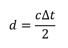
One way to do amplitude modulation is to send out a short pulse. This is called direct time-of-flight (dToF) and is very intuitive and easy to explain. It is also called pToF sometimes (pulse time-of-flight). Because the speed of light is a constant we can send out a short pulse and measure the time for the pulse to come back. The distance to the object is given by the speed of light times the measured time divided by two (since light goes back and forth):

For a 1 ns time, the distance is 15 cm which is a number that can be good to memorize. This technique is often referred to as direct detection as well.
The other way to do time-of-flight is the indirect way. Indirect time-of-flight (iToF) uses a phase modulation of the amplitude. NOTE: not a modulation of the phase of light! By modulating the light source with a certain frequency (MHzs) and modulating the receiver with the same frequency, it is possible to detect the phase of the light when it returns. The phase corresponds to the distance. Everything is very well described here: https://devblogs.microsoft.com/azure-depth-platform/understanding-indirect-tof-depth-sensing/
This method is very well established and is used in most laser rangefinders available commercially. No fancy detectors or pulse generators are needed so it can be made quite cheap.
RMCW – random modulated continuous wave, is a kind of amplitude modulation. The amplitude is modulated in a quasi-random way which is non-repetitive. The light can be auto-correlated to a digital or analog twin and the distance can be decoded from where the two signals give the strongest overlap. Here is an example of the random pattern (ref. Xu et al, https://doi.org/10.3390/photonics8110475).

A benefit is that this light will be less prone to interference with other types of LiDARs.
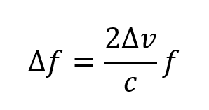
Often though, one wants to also know the velocity of the object you are looking at. You can in principle do this with a ToF LiDAR by measuring multiple points and taking the difference in distance. But it is not particularly fast or precise. It is better to use the Doppler effect. For a LiDAR, the Doppler shift is given by

A factor of two comes from that the signal is reflected off from the moving object (as opposed to a moving source). For an object moving with a velocity of 100 km/h, this shift is 100 Mhz (or 0.01 pm in wavelength) for 550 nm light. This is very small! So, to measure it we need to mix the return signal in amplitude with some type of reference. The result will vary in amplitude with the frequency shift. For RMCW, the result will look like this:

This is easily detectable by standard photodiodes! The velocity can be found by Fourier analysis in the frequency space. This means that all coherent detection techniques can measure velocity. But note! Only in the radial direction! For lateral movement, there will be no shift of the frequency.
Radar has been around much longer than LiDAR and since the 1940s, frequency modulation has been used for distance measurement. It is also used for LiDAR in so-called FMCW (frequency modulated continuous wave) detection. The frequency is shifted with time so different frequency shifts between the reference and the signal corresponds to different distances. The frequency shift detection requires (just as for Doppler) a coherent detection. The modulation can be done in different ways, for example as a sawtooth. It needs to be in both directions, in order to differentiate the frequency modulation shift from the Doppler shift, and also find the direction of the objects relative velocity.
This technique is also called heterodyne detection (different wavelengths) and is used in other applications as well.
Here are some other words and acronyms that are helpful in LiDAR:
Flash LiDAR: A type of ToF (indirect or direct) that illuminates a part or the full field-of-view at once and then uses an array to detect distance in that area.
FPA: Focal plane array. An array placed in the focal plane of a lens, which makes each pixel or point in the array correspond to an angle.
FOV: Field-of-view, sometimes VFOV, HFOV, and DFOV refers to vertical, horisontal and diagonal field-of-view.
Near limit: The closest detectable distance. For a dTOF this can be limited by parallax shift due to separation between detector and transmitter, or from the zero pulse.
Link budget: The calculation of range for a LiDAR (photon budget).
PIC: Photonic integrated circuit. The equivalent of a PCB for photonics, where optical components are placed on a chip.
SPAD: Single-photon avalanche diode. An avalanche diode set in a high bias, so that each photon gives a very strong signal amplification. Used widely in dToF LiDARs.
Zero pulse: The direct, internal light in a LiDAR that will blind the detector for the first few nanoseconds. In a biaxial system this may not be present.
References and additional reading
Time of Flight vs. FMCW LiDAR: A Side-by-Side Comparison, https://www.aeye.ai/resources/white-papers/time-of-flight-vs-fmcw-lidar-a-side-by-side-comparison/
LiDAR and other Techniques, Slawomir Piatek, https://www.hamamatsu.com/content/dam/hamamatsu-photonics/sites/static/hc/resources/W0004/lidar_webinar_12.6.17.pdf
Understanding Indirect ToF Depth Sensing, https://devblogs.microsoft.com/azure-depth-platform/understanding-indirect-tof-depth-sensing/

