Lightguides – shape and performance – part 1
By Billy Kaldvee |
Have you ever done a mechanical design of a light guide without doing any optical simulations and wondered why the result looked as something you did not expect? In two posts we go through some of the basic aspects of light guide geometries and how they influence the perceived output.
In this first post we go through
– Influence of the geometrical shape of the cross section.
– Light guide radius of curvature
– Fresnel reflection limitation
In the second post, the following subjects will be discussed
– LED distance to light guide
– Tolerancing of lateral and axial LED position
– Output angular distribution
– Mechanical holder for light guide
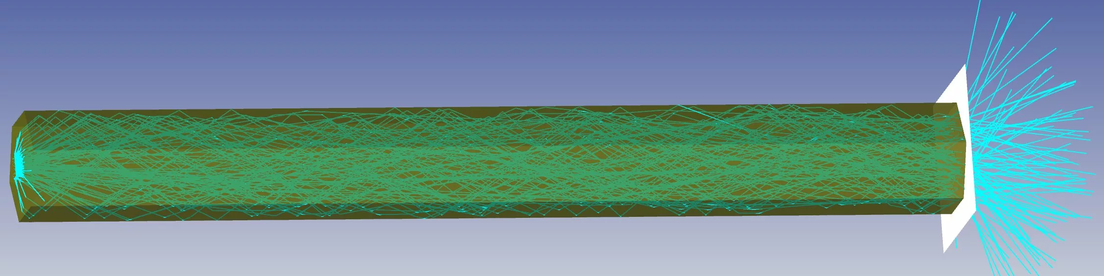
First, we consider the light guide cross section. For straight light guides, the geometrical cross section may have a huge impact on the light distribution after the final surface. An example is shown in figure 1, where 25 mm long light guides with 3 mm cross section diameters are used exploring circular, hexagonal and square cross-sections. The light source is a 0.3×0.6 mm homogenous emitting surface with Lambertian angular distribution to simulate a common standard LED output.
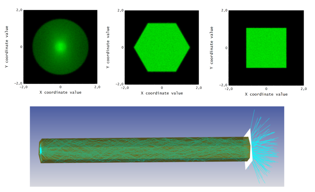
Figure 1: Light distribution after the end surface of a circular, a hexagonal, and a square light guide.
As seen in the top of Figure 1, which shows the illuminance (lumen/m2) after the end surfaces of the light guides, the light is almost magically redistributed in the hexagonal and square light guides. Their cross sections have very uniform intensity profiles, while the circular light guide gets a hot spot in the center. Here we learn that using a non-circular cross section could be very important for a short straight light guide (this is also the case for most other longer bent light guides with high coupling efficiency).
Another way to break the symmetry of the cylindrical light guide is to introduce a curvature. The challenge that is faced when bends are used is that light often leaks out. In Figure 2 below, the circular light guide has a bend radius of 5 mm. In this case, only 60% of the light is nominally coupled out from the source through the end surface. This should be compared to 84% in the straight circular light guide. By increasing the radius of curvature to 10 mm the efficiency is increased to 76% while still having a decent uniformity at the end surface, see Figure 3. On the other hand, decreasing the radius to 2 mm decreases the efficiency to 22% and two ugly dark spots can be seen on the end surface, see Figure 4.
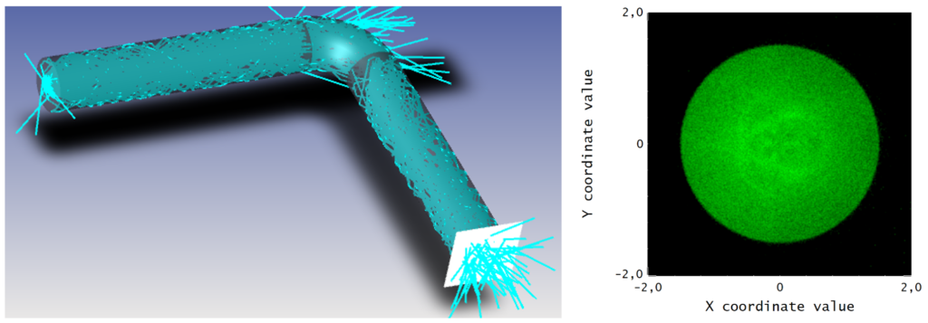
Figure 2: A light guide with a bend mixes the light much better on the output surface. Radius of curvature 5 mm.
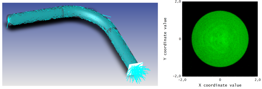
Figure 3: Light guide with a 10 mm radius of curvature.
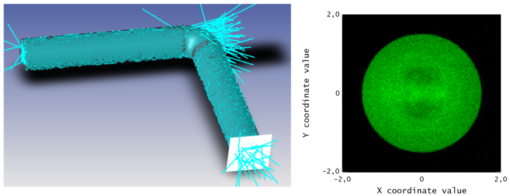
Figure 4: Light guide with a 2 mm radius of curvature.
If you want to minimize the leakage of light from a bent light guide when passing through it, it is obvious that a larger radius of curvature is needed. Unfortunately, when increasing the radius to minimize the losses for a circular cross section we start to get the same hotspot in the center as we had for the straight circular lightguide. Then, again, if we want a good efficiency together with a homogenous illumination after the end surface, we need to use a non-circular cross section and a large bend radius.
If it is possible, use a radius of curvature 10 times larger than the radius of the cross section of the light guide to achieve high efficiency. In our example that would be a radius of curvature of 15 mm which gives an efficiency of 79 % to be compared with the maximum nominal 84% for the straight light guide. In Figure 5 the coupling efficiency as a function of radius of curvature is shown for our circular light guide with 1.5 mm cross section radius.
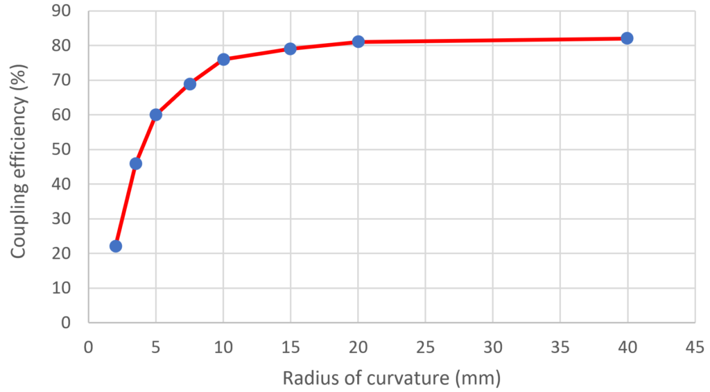
Figure 5: The coupling efficiency for a circular light guide with 1.5 mm cross section radius.
But is there anything we can do to push the 84% efficiency even further? First, we can investigate why we have 84% in our nominal design. A close-up view of the LED surface which is positioned only 0.2 mm from the surface shows, as we would expect, that light with very high angles out from the LED will still hit the light guide. Actually, in our setup >98% of all rays leaving the LED hit the 3 mm diameter cross section of the light guide. As can be seen in Figure 6, only a few rays at large angles will miss the entrance surface of the light guide.
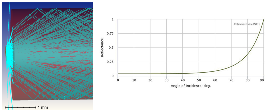
Figure 6: Close-up view of the LED positioned 0.2 mm from the light guide and a graph showing the reflectance of light passing from air to PMMA at different angles of incidence.
The problem we are really struggling with is the Fresnel reflectance when the light passes between air and the light guide material. For PMMA, used in our example, the reflectance is around 4% up to an incident angle of 40°. This will decrease both the amount of light being transmitted into the light guide and the amount of light being transmitted out of the light guide at the end surface. The reflectance starts to increase dramatically after 70°, as seen in Figure 6, and is a major obstacle when trying to couple light into the light guide at high incidence angles. The transmission from air to PMMA can be increased by adding an antireflective (AR) coating on the surface, but that will drastically increase the price of the initially cheap and simple light guide component which you probably in most cases would like to mass produce with a molding tool.
Note that there are different design targets for different applications of the light guides. sometimes there is a need to transport as much light as possible from the LED to the output surface to have a high efficiency. But in other cases, the challenge is more about dealing with what happens with the leaking light. The leaking light may give you stray light ending up at places where it disturbs the visual effect or the function of your system.
To achieve a high efficiency system, it is important to keep the distance from the LED to the light guide small in comparison to the cross section of the light guide. If you want to couple a fair amount of the LED light (>80% for an uncoated light guide) it is recommended to keep the LED to light guide distance ten times smaller than the light guide cross section diameter. Keep in mind that it is assumed that the LED is substantially smaller than the light guide for these approximations to be true.
In the next post we will demonstrate why it is recommended to keep the distance ten times smaller than the cross-section diameter by showing simulation results of how the distance between the LED and the light guide affects the coupling efficiency. We will also elaborate on the lateral position tolerance in relation to the distance tolerance, take a look at the angular distribution of the light out from the light guide, and say a few words about some things to think about when designing a holder for your light guide. So, keep your eyes open for the next post!