Speckles and their likelihood of detection
By Olov von Hofsten| Speckles are something that I have always been fascinated by. When I saw them for the first time, during school, they didn’t look like anything I had ever seen before. The pattern of bright dots moves with your position as if they are floating in space and you cannot focus on them. I still find it mesmerizing. In this article I will explain some basics about speckles and touch on the target of speckle statistics. We will see that the probability of detecting them is surprisingly low…
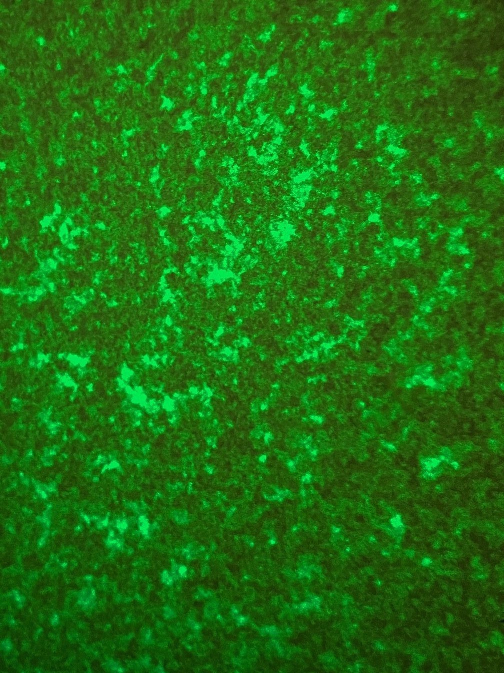
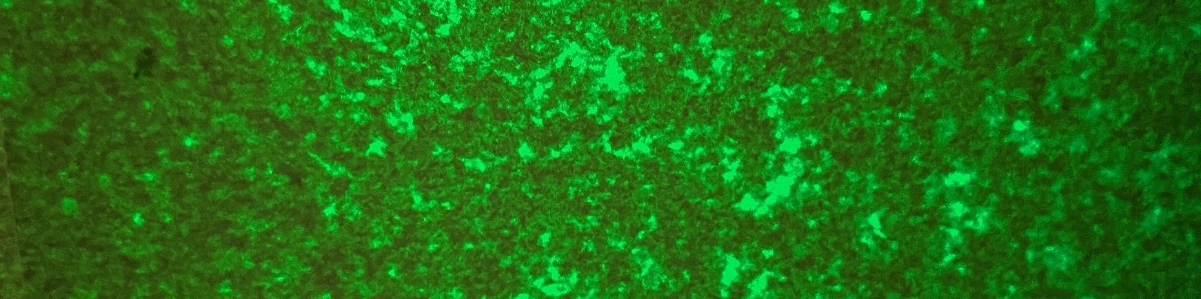
Figure 1: Example of a speckle pattern
Speckles arise from the interference of light scattered from different areas of a surface hit by coherent light. If the surface irregularities are randomly oriented, they will sometimes give constructive interference (and give a bright point) and sometimes destructive (which gives a dark point). Figure 2 shows how this works. The different structures that build up the speckle pattern are called speckle grains. The shape of the grain varies, sometimes they are round and sometimes they look more elongated, like cigars.
Mathematically, the pattern is expressed as
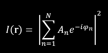
Where An is the amplitude of the n-th scattered wave and Φn the phase. N is the number of points, or scattering centers.
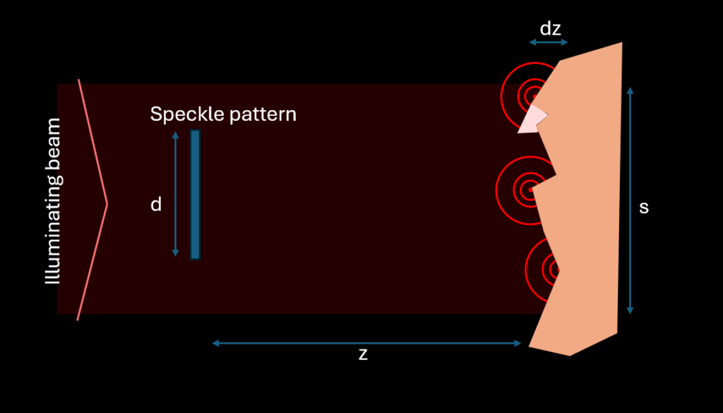
Figure 2. A laser beam illuminates the rough surface on the right. Over the area s, points scatter coherent light which ends up interfering with each other in the speckle pattern at a distance z. The roughness of the surface, dz, needs to be larger than the half the wavelength but shorter than the coherence length – for high contrast (or fully developed) speckles.
The surface needs to have a roughness which is larger than half the wavelength of the laser light. If the roughness is too small, the phase difference of the points is not enough to be out of phase with each other and the speckle pattern will not be fully developed. Secondly, the coherence length of the laser needs to be longer than the roughness otherwise different light from different points will not be able to interfere with each other.
For most surfaces and for most lasers, this requirement is fulfilled! Which is why we usually see speckles. Try it yourself, use a laser pointer on your living room wall. If you can’t see them – you may need to turn down the lights in your room. The speckles are much less bright than the illuminated laser spot. It is also worth noting that, since speckles are a wave phenomenon, speckles are also seen in ultrasound and in radio waves.
Speckles are divided in “objective” and “subjective”. The difference is that objective speckles will look the same for any observer – imagine putting up a paper to collect the speckles (like in figure 2). Subjective speckles depend on the observer: the type of lens and aperture etc. These are the ones formed in your eyes – which I mentioned in the beginning of the article.
The size of the speckle grains depends on the wavelength of light and the angle of the laser spot to the observation plane. Not on the surface! Which is perhaps a bit surprising. A small spot at a large distance will give the biggest speckles, whereas a large spot at a short distance will give small speckles. In fact, it is a great way to focus a laser. There is a nice youtube clip showing this here: https://www.youtube.com/watch?v=NV4HpzAl63Y
The size is roughly given by λ/α, where the angle α=s/z, which gives
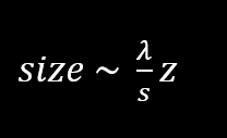
See figure 2 for explanations of the variables. For subjective speckles, the size instead depends on the aperture size (replace for s) and the focal length (replace for s). The exact pattern depends on the roughness of the surface, and even a very small movement or changes of the surface will give rise to changes in the pattern. This is utilized in applications like thermal studies and vibration. As the target moves, surface areas which were previously not illuminated will come into the beam and others will leave. If you move the surface slowly, you see intensity moving between different maximums of the speckle pattern, which is very fascinating. Very small movements can be detected in this way.
To illustrate the size of the speckle patterns, I wrote a small Python-script that calculates speckles for different geometries and wavelengths. You can access it via this link: https://eclipseoptics.com/speckle-visualizer/ (thanks to Jonas Claesson for helping me fix that)
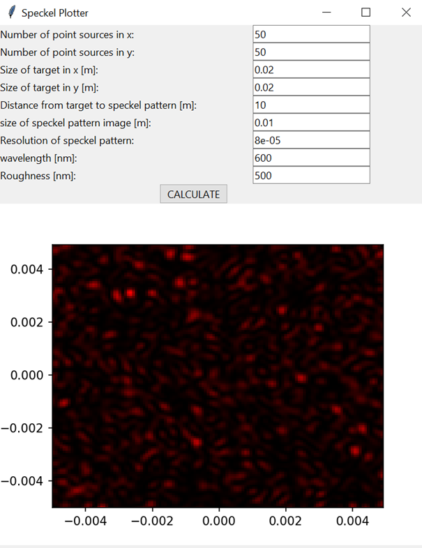
Interface of the speckle generator. “Number of points” is the number of waves or scattering centers at the target. “Size of target” is the size of the target (s in figure 2) and “size of speckle pattern” is the observed area of the (objective) speckle pattern.
Let me know if you want a copy of the script!
One thing you might notice in the speckle pattern is that most of the area is black or dark. It is better illustrated if we plot a histogram of all the pixel values:
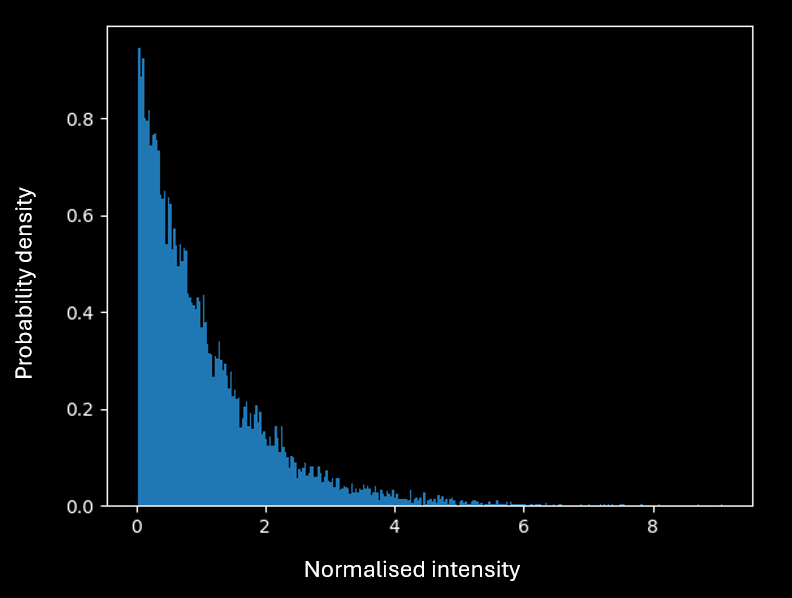
Figure 3. Histogram plot of pixel values in a simulated speckle pattern. The most probable value is 0.
So when trying to detect a speckle pattern you will most likely detect – nothing at all. Note though, that even if the most probable value is 0 – there is a higher chance that you will find a non-zero value. This is in line with the theory. Speckle statistics follow negative exponential distribution. The probability density function (PDF) is given by:
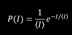
<I> is the expected value and I is a possible intensity value. As one can see from this, N=0 is the most probable outcome. But there are some points with very high intensity. This is how the theoretical probability plots to different values:
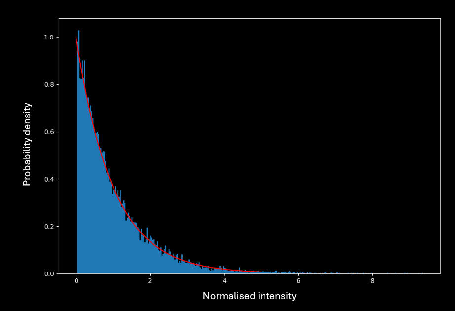
Figure 4. Theoretical probability distribution of speckle noise with <I> = 1 plotted with the data from figure 3.
This may look bad. Integrating up to the expected value, it is clear that the probability of getting a lower signal than expected is 63% (one sigma). This is even clearer if we rewrite this into a loss distribution function. We define loss as
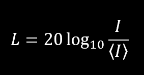
This function plots like this
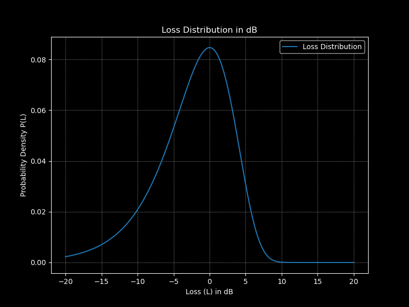
Figure 5. Recalculated probability with dB loss. Note that a positive dB loss is actually a gain, which may feel confusing!
Again, we see that the probability of getting a lower value than expected is 63% and 37% of getting a higher value (a gain). However, since the higher values compensate by being a lot higher, containing more energy in each high intensity speckle. This ensures that energy is conserved. And of course, the average of the speckle pattern is the expected value.
Speckles can be a problem in coherent detection systems, like FMCW LiDAR. What comes back to the receiver is not a nice spot but a speckle pattern and the pattern is sampled by the receiving aperture. This is a significant source of noise in many systems and needs to be considered in any link budget. Repeated measurements can reduce the noise, be it over time, space, polarization or wavelength but it comes at a cost of lower highs.
Summary
Speckles are great and fascinating, and the statistics of them can be hard to wrap your head around. I hope I brought some light to your understanding of speckles. But the best way to understand them is to get some hands-on experience in the lab. The two listed experiments (focusing a laser point and moving your target while observing the speckle pattern) are a good way to start! What do you more want to know about speckles? Let me know!
Leave a Reply