Lightguides – shape and performance – part 2
By Billy Kaldvee |
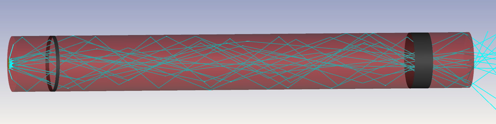
In the last post we recommended to keep the distance between the LED and the light guide ten times smaller than the light guide diameter. To demonstrate why this is recommended for a high efficiency system, we once again do simulations on the 3 mm diameter circular light guide with the 0.3×0.6 mm LED. In Figure 7 the blue curve illustrates how much of the light from the LED that reaches the light guide surface as a function of the distance. The orange curve shows the light guide coupling efficiency, i.e. the fraction of the light that actually leaves the end surface of the light guide. The coupling efficiency follows the amount of light reaching the surface of the light guide. But bringing the LED closer than 0.3 mm gives a very small increase in coupling efficiency. The limited effect is due to the very high Fresnel reflectance for higher angles as was shown in Figure 6 of the previous post.
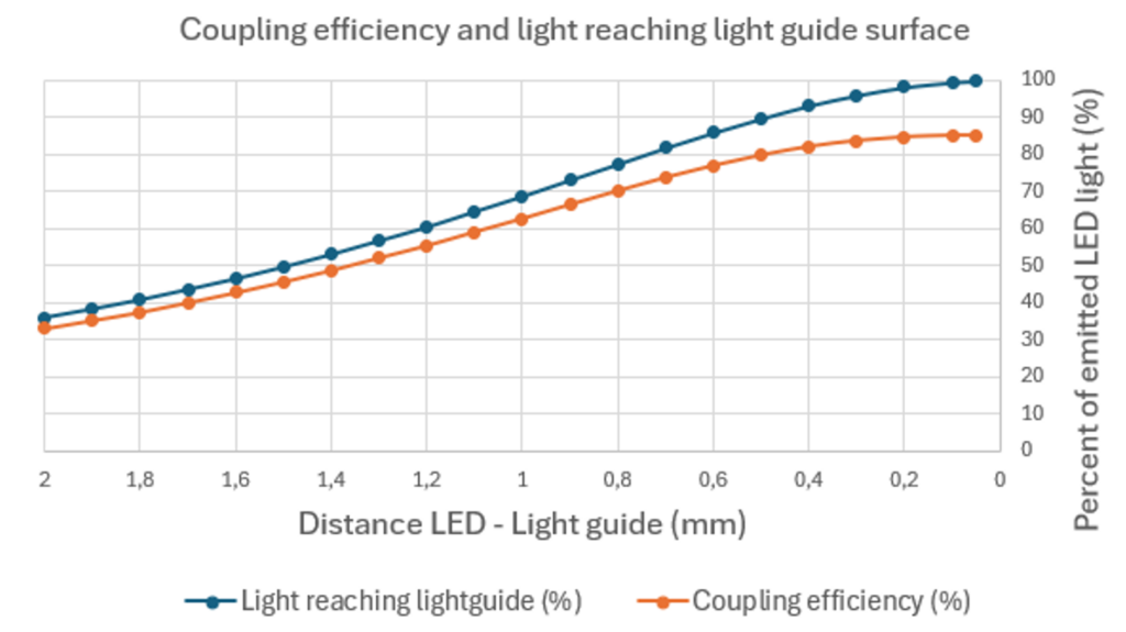
Figure 7: The amount of light reaching the light guide surface and the coupling efficiency from LED to light guide output as a function of the distance between LED and light guide.
When the distance is long, the cone angle of the light reaching the light guide becomes small, see distance, d, and cone angle, α1, in Figure 8. At 2 mm distance the cone angle is 37°. For all angles < 37°, the Fresnel reflection is around 4% as seen in Figure 6. A rough guess would then be that with the Fresnel reflections at both the in- and out surface of the light guide, 0.96×0.96 = 92% of the light that hits the incoupling surface of the light guide would actually leave the end surface of the light guide. The simulation confirms that the ratio of the orange and blue curve is 92% at 2 mm distance. Remember that the coupling efficiency is only 33% at this distance due to the small cone angle of the LED light reaching the light guide, which means that a lot of light will pass outside the light guide and contribute to stray light in the design.
When moving the LED closer to the light guide, the cone angle will increase. The Fresnel reflection for these rays is higher, e.g. at 70° the reflection is 25%. This decreases the fraction of the light passing through from in- to out surface of the light guide to 86% when being at a close 0.1 mm distance. As discussed previously only a small increase in total throughput is seen when decreasing the distance to shorter than 0.3 mm. From a design perspective this could be important to know when tolerancing the position of the LED surface in relation to the light guide. For this specific design it would be a good optical design to allow the tolerance to keep the distance smaller than 0.3 mm. To accommodate the largest possible tolerance the nominal distance should be set to 0.15 mm which allows for a tolerance of ±0.15 mm.
If, e.g., the mechanical design only allows the distance to be minimum 1 mm, the coupling efficiency dramatically decreases to around 60%. From the rule of thumb, we know that it should be recommended to increase the cross section of the light guide to 1 mm × 10 = 10 mm if a high coupling efficiency is wanted, which could be a quick useful input to your project.
So, what about the lateral positioning tolerance? How good will the LED need to be centered? Let’s do a simplified approach assuming that the LED is a point source. Figure 8 illustrates the geometrical relationships. As a test example we use the previous design with a 3 mm diameter light guide and assume that we manage to position the LED at 0.1 mm distance with a tight tolerance. In the previous discussion we considered a 0.3 mm distance to be good enough for the coupling efficiency. At this distance, d = 0.3 mm, the cone angle, α3, will be 79°. When a lateral offset Δh is introduced in our design having the distance d = 0.1 mm, the offset can be increased to 1 mm before the cone angle α2 reaches 79°. Notice that 1 mm is a large offset for a 1.5 mm radius light guide, which may feel a bit unintuitive.
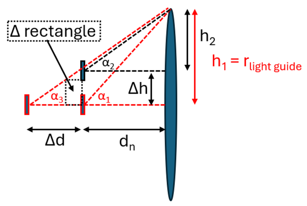
Figure 8: Lateral tolerancing, Δh, in relation to the distance, d, and the dependence on light guide radius.
The simple idea is to let the cone angle, α, be >79° to collect at least the same cone of light from the light source. This corresponds to h/d > 5, schematically represented by the triangles with α2 and α3 in Figure 8. Visually, the tolerances are represented by the “Δ rectangle”, which has the lower right corner in the nominal LED design position. The rectangle is limited to stay within the α3 triangle but can have any relation between Δh and Δd.
To verify that the simplified back-of-the-envelope calculation is correct, a simulation is done with d = 0.1 mm and Δh = 1 mm. The coupling efficiency for this geometry is 87.4%, which is, as we assumed, better than the 83.7% for the reference design with d = 0.3 mm.
If it is a struggle to keep all the mechanical tolerances it can be a relief to know that for a high efficiency design the lateral tolerances generally can be kept looser if the sensitive distance tolerance can be well controlled. Don’t forget that the LED active surface often has general tolerances of 0.1 mm in all directions, which is a limitation for the positioning if no active alignment of the component will be done.
If no diffusing material is used at the outcoupling end of the light guide it is very important to know what the angular distribution of the light coming out from the light guide will be. Otherwise, it could end up showing intensity dips for viewers at positions where it is not wanted. And actually, as mentioned in a previous blog post about simulating luminance in Zemax, the angular peaks often are real or virtual images of the LED when looking into the light guide. As soon as bends on the light guide are introduced or mechanical parts to hold the light guide are used, they will lead to patterns in the angular distribution.
To visualize the effect on the angular distribution, a high efficiency bent circular light guide with 1.5 mm radius and 20 mm radius of curvature is used. For a curved light guide we have learnt that the distribution on the end surface will have some kind of hot spot in the center. This is shown by the simulation result in the upper part of Figure 9. The angular distribution is a pattern of peaks and valleys since the light has travelled along the bend of the light guide. At e.g. -15° in the horizontal direction there will be a large dip which may be unwanted if a viewer is expected to be in that position or move between -18 and ‑54° as that will cause a perceived fluctuation of the light intensity. To create a smoother intensity distribution on the surface, the last part of the light guide is made with a hexagonal cross section. As expected, the illumination from the end surface becomes very smooth and evenly distributed, and one could be misled to believe that the angular distribution should also become smooth. But, as can be seen in the lower right part of the figure, the angular distribution still has a very sharp pattern with the same major features as the circular light guide had. To achieve a more uniform angular distribution from this light guide, a diffusing component with an angular spread larger than the dips will be needed at the end of the light guide.
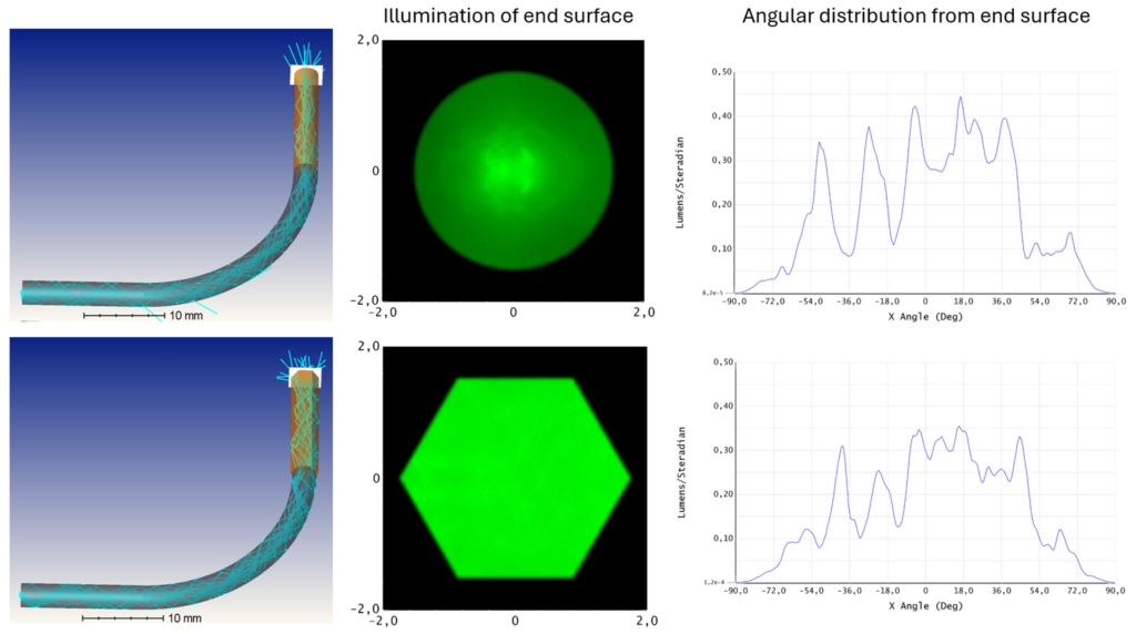
Figure 9: Light guide with 1.5 mm radius and 20 mm radius of curvature with circular or hexagonal end part. The illumination of the end surface and the horizontal cross section of the angular distribution of light out from the end surface is shown.
If mechanical support for the light guide is needed it is best from an optical perspective to make the contact areas as small as possible to avoid light leakage. Light leakage will both decrease the coupling efficiency and disturb the angular distribution of the light coming out from the light guide. In the example below in Figure 10, a 1 mm wide holding ring is used to illustrate what will happen if a leakage is introduced at the mechanical contact area.
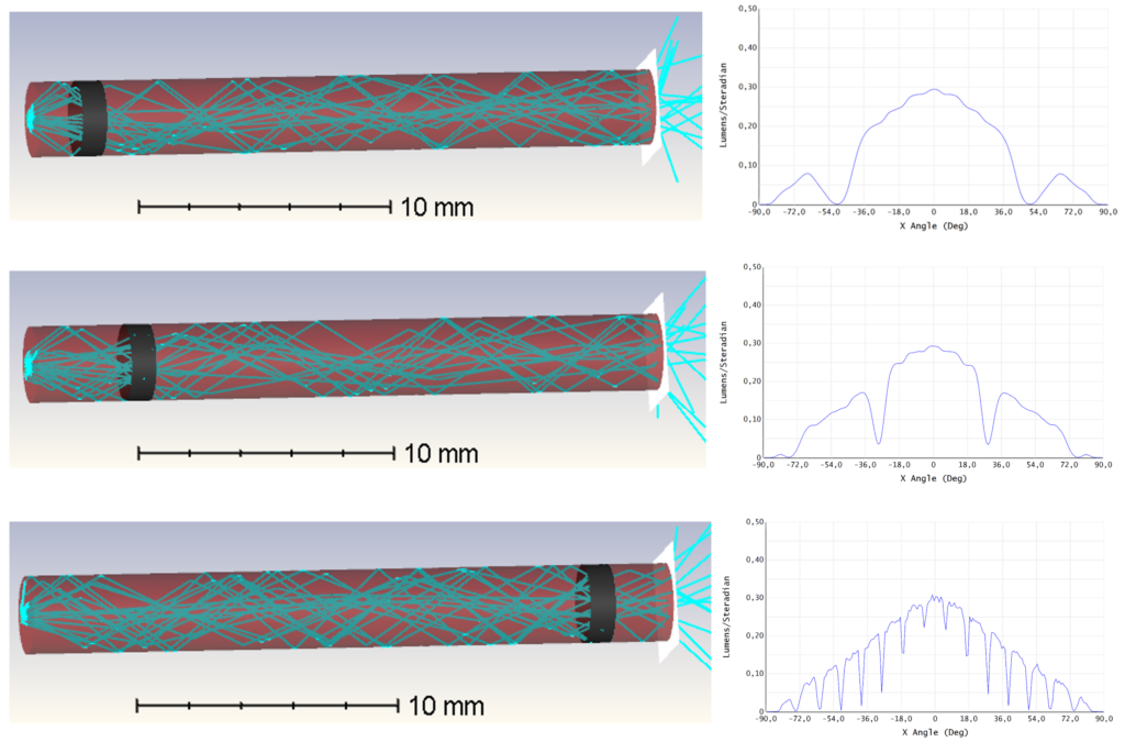
Figure 10: A circular light guide with a 1 cm wide holding ring absorbing the light in the contact area.
Without a holding ring the coupling efficiency for this light guide geometry is 85%. With a holder, the coupling efficiency shifts from 59% to 70% when moving the holding ring from a 3 mm to a 23 mm distance from the incoupling surface. From that perspective, it is better to have a holding structure further down the light guide if possible. The angular distribution from the 23 mm position shows a fine structure of valleys which will be easier to redistribute with a diffusing material having a smaller angular spread, hence a higher transmission, at the end of the light guide.
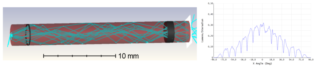
Figure 11: Suggestion for a design with two holders with the one early in the light path having a smaller contact area.
There are, of course, an infinite number of ways to design your light guide and your mechanical holders. In Figure 11, a design with two holders is shown. The first holder early in the light path is made smaller, 0.2 mm wide, to decrease the overall light loss through the light guide. It is also positioned so that the angular dip is at the same angle as one of the smaller dips from the second holder, showing as a wider shallow dip around 45-50°. With this approach, the coupling efficiency for the light guide is 66%.
To summarize what we have learned in both part 1 and part 2:
- Use a non-circular cross section for a uniform intensity distribution, at least in the last part of the light guide.
- When bending the light guide, use a radius of curvature ten times larger than the cross section radius of the light guide for a high coupling efficiency and to avoid straylight from leakages.
- Keep the distance between LED and light guide ten times smaller than the cross section diameter to have a high coupling efficiency and prevent light from missing the light guide, hence contributing to unwanted stray light.
- For most designs, it is possible to have a rather loose tolerance on the lateral LED positioning when the distance to the light guide is well controlled.
- For almost all complex light guide shapes, a diffusing material will be needed at the end of the light guide to achieve an even angular light distribution and to get rid of direct and mirror images of the LED.
- The mechanical holders for the light guide will affect both the coupling efficiency and the angular distribution, hence the contact area should be kept to a minimum. Generally, it is better to have the holders at the end of the light guide and if several holders are needed the ones with larger contact areas should be at the end.
Let me know if you have any questions or comments on this blog!